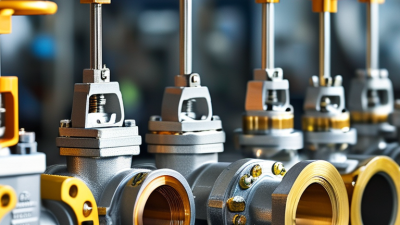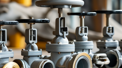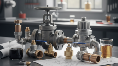
What Are Guide Valves and How Do They Work?

Guide valves sit where fluid movement, mechanical guidance, and process safety meet. The term is not always used consistently. It may describe a valve with a guided plug or stem, or a device that directs flow through a controlled passage. That ambiguity matters. A reliable explanation must define the design before discussing performance.

Industry data shows why these components deserve closer attention. Fortune Business Insights’ 2024 Control Valves Market report identifies expanding demand across oil and gas, power generation, chemicals, water treatment, and manufacturing. MarketsandMarkets also links market growth to automation, predictive maintenance, and digital valve monitoring. These reports discuss control valves broadly, but they provide useful context for guide valves. Their value depends on accurate sizing, suitable materials, stable actuation, and disciplined maintenance.

Dr. Greg McMillan, a respected process-control author, states, “The control valve is the most important final control element in the process industry.” His observation explains the practical role of guide valves. A sensor may detect pressure changes, but the valve changes the process physically. Inside the body, guiding surfaces help keep movement aligned. This can reduce vibration, uneven wear, leakage, and unstable flow. Small details decide.

This guide examines how guide valves work, where they are installed, and which factors influence their service life. It will also consider pressure drop, cavitation, actuator selection, sealing, inspection, and failure symptoms. Some explanations may appear simple. Real systems are not. Temperature, contamination, incorrect installation, and neglected calibration can overturn an otherwise sound design. That is why specifications should be checked against manufacturer data, recognized engineering practices, and site experience.
What Are Guide Valves and How Do They Work?

Guide Valve Definition: Guidance, Flow Control, and Main Applications

A guide valve is a precision component that keeps a moving spool, stem, or poppet aligned while controlling fluid direction and volume. Its name varies across industries, so specifications matter. In hydraulic equipment, a guide valve may position a control element through pilot pressure. The element then opens, restricts, or redirects oil through small passages. In engine systems, a valve guide mainly supports the stem. It does not control flow alone.

Clear alignment reduces friction, uneven wear, and leakage. However, guide valves still need correct clearance, surface hardness, and compatible fluids. A small misalignment can create vibration, heat, or delayed actuator movement. MarketsandMarkets reported that the global industrial valves market could grow from about 78.5 billion dollars in 2023 to 98.5 billion dollars by 2028. This expansion reflects wider demand for reliable flow control in water treatment, energy, manufacturing, and process equipment. The figure is useful, but market forecasts are not guarantees.

Tips: Check the valve’s pressure, temperature, and flow ratings before installation. Inspect the guide surface for scoring and contamination. Measure response time during commissioning. Do not assume a familiar shape means identical operation. I have seen maintenance teams replace seals first, although poor alignment caused the repeated failure. That mistake is easy to miss. Industry standards, maintenance records, and manufacturer-neutral testing should support the final selection.

Core Parts Explained: Body, Stem, Seat, Actuator, and Guide Mechanism

What Are Guide Valves and How Do They Work?

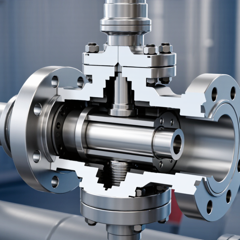
A guide valve controls fluid flow by moving a closure element along a guided path. Its body contains pressure and provides the flow passage. Inside, the stem transfers movement from the actuator to the valve plug or disc. The seat creates the sealing surface. Even a small scratch can cause leakage, noise, or unstable control. The actuator supplies force through pneumatic, electric, or hydraulic movement. The guide mechanism keeps the stem and closure element aligned during repeated cycles.

The guide mechanism is often the quiet workhorse. It reduces side loading and limits vibration when pressure changes quickly. In steam and process systems, this alignment supports more predictable throttling. The U.S. Department of Energy’s Improving Compressed Air System Performance report notes that leakage can waste 20–30% of compressor capacity in poorly maintained systems. A correctly selected guide valve cannot fix every leak, but it can improve isolation and response. Field inspections still matter. Designers sometimes trust catalogue data too much.

Tips: Check the seat material against temperature and fluid chemistry. Measure stem movement, actuator force, and packing condition during maintenance. Look for uneven wear on the guide surfaces. The U.S. Department of Energy also recommends routine leak detection and repair, often using ultrasonic testing. Do not ignore a faint hiss. It may indicate a larger efficiency problem. One practical limitation remains: guide valves can resist contamination poorly, especially when fine particles enter narrow clearances. Regular filtration and realistic maintenance intervals are essential.

How Guide Valves Work: From Actuator Input to Controlled Flow Movement

What Are Guide Valves and How Do They Work?

How Guide Valves Work: From Actuator Input to Controlled Flow Movement

A guide valve converts actuator force into controlled movement inside a flow passage. When a signal reaches the actuator, air pressure, electric torque, or hydraulic force moves the stem. The stem carries the plug, disc, or guided element toward or away from its seat. Small movement matters. The guide keeps this element aligned, reducing side loading and helping the valve respond predictably.

As the opening changes, the available flow area changes too. Pressure drops across the restricted passage, while fluid velocity rises locally. The resulting flow depends on valve geometry, fluid properties, upstream pressure, and downstream demand. A calibrated positioner may compare the requested position with actual stem travel. It then corrects the actuator signal when friction, pressure forces, or temperature cause deviation. That feedback is practical, not decorative.

During commissioning, technicians watch travel, leakage, noise, and response time under real operating conditions. A valve can reach its target position yet control poorly if the trim is damaged or sizing is unsuitable. Operators may also observe hunting when actuator gain is too high or feedback is delayed. The calculation may look exact, but field behavior is less tidy. This is where specifications deserve a second look.

How Guide Valves Work: From Actuator Input to Controlled Flow Movement

This normalized operating profile shows how an actuator command moves the guide valve stem or spool and changes the controlled flow rate. The values represent a typical linear-response guide valve; actual performance varies with valve geometry, fluid pressure, and system resistance.

As the actuator signal increases, the valve opening moves progressively farther from the closed position, allowing a greater flow area and higher relative flow rate.

Pressure and Temperature Limits Under ASME B16.34 Class Ratings

What Are Guide Valves and How Do They Work?

A guide valve uses a guided plug, piston, or stem to control fluid movement accurately. The guide keeps the closing element centered during operation. This reduces vibration, uneven wear, and unstable throttling. In field inspections, poor alignment often appears as scoring on the stem or seat. Small damage can become a serious leakage path.

Pressure and Temperature Limits Under ASME B16.34 Class Ratings

ASME B16.34 pressure-temperature classes define allowable pressure for specified valve materials and temperatures. Class 150 does not mean the valve always handles 150 psi. That assumption is common, but it is unsafe. The permitted pressure changes with material group, design temperature, valve construction, and the applicable standard edition.

As temperature rises, pressure capacity usually falls. A Class 600 valve may therefore require a lower working pressure near its upper temperature limit. Engineers should read the correct pressure-temperature table, not rely on the class number alone. They should also check trim materials, body ratings, end connections, and thermal cycling. A valve exposed to hot steam can experience rapid expansion around the guide area. That may affect clearances and operating force. Actual service conditions matter.

The rating is not a substitute for system analysis. Corrosion, erosion, fluid density, and pressure spikes can reduce practical reliability. I have seen specifications that matched pressure but ignored temperature transients. That gap deserves review. Procurement documents should state the medium, minimum and maximum temperatures, design pressure, cycling frequency, and required testing.

What Are Guide Valves and How Do They Work? — Pressure and Temperature Limits Under ASME B16.34 Class Ratings
Category Component or Rating Typical Value or Function How It Works or What It Means
Guide Valve Operating Principles
Valve function Guide valve Guides and stabilizes the movement of a valve stem, piston, or plug A guide controls lateral movement and helps maintain accurate alignment between the moving closure element and the seat.
Primary purpose Stem or piston guidance Reduces side loading, vibration, and uneven wear The guided element moves along a defined axis, improving repeatability and reducing the risk of misalignment during opening and closing.
Flow control Opening and closing movement Linear or guided axial movement When the actuator applies force, the guide keeps the stem, piston, or plug centered while the closure element regulates or stops flow.
Typical applications Control, isolation, and pressure-regulating valves Steam, water, hydrocarbons, gases, and process fluids The exact design depends on fluid properties, pressure drop, temperature, leakage requirements, and actuator configuration.
Common guide features Guide bushings, guide ribs, cages, or drilled guides Machined metal or compatible wear-resistant materials The guide surface supports the moving member while allowing the required travel without excessive friction or binding.
Actuation Manual, pneumatic, hydraulic, or electric Actuator force is transferred through the stem or piston The actuator changes the position of the closure element; the guide maintains alignment throughout the complete stroke.
ASME B16.34 Pressure Class Reference
Rating basis ASME B16.34 Class rating Pressure-temperature rating system The class number is not a direct pressure value. The allowable pressure depends on temperature, material group, valve construction, and the applicable edition of the standard.
Material reference Carbon steel, ASTM A216 WCB, material Group 1.1 Reference material for the values below The figures are representative ASME B16.34 pressure-temperature ratings for a common carbon-steel material group and must be verified against the valve material and governing edition.
Temperature reference 100°F / 38°C Allowable pressure at the reference temperature At temperatures above the reference point, allowable pressure generally decreases because material strength and design limits are temperature-dependent.
Pressure class Class 150 285 psi / 19.6 bar at 100°F / 38°C Suitable only when the selected material, valve design, temperature, and end connection requirements support this rating.
Pressure class Class 300 740 psi / 51.0 bar at 100°F / 38°C Provides a higher pressure rating than Class 150, but the allowable pressure still changes with temperature and material group.
Pressure class Class 600 1,480 psi / 102.1 bar at 100°F / 38°C Commonly used for higher-pressure services where the valve body, trim, bolting, and connections are rated accordingly.
Pressure class Class 900 2,220 psi / 153.1 bar at 100°F / 38°C Designed for high-pressure service; installation must account for flange, piping, gasket, and bolting compatibility.
Pressure class Class 1500 3,705 psi / 255.5 bar at 100°F / 38°C Used for very high-pressure applications with appropriate materials, wall thickness, trim, and testing requirements.
Pressure class Class 2500 6,170 psi / 425.4 bar at 100°F / 38°C The highest commonly listed ASME B16.34 pressure class; actual service limits require detailed design verification.
Illustrative Pressure Derating with Temperature
Carbon steel Group 1.1 Class 150 at 500°F / 260°C 170 psi / 11.7 bar Compared with 285 psi at 100°F / 38°C, the allowable pressure is reduced as temperature increases.
Carbon steel Group 1.1 Class 300 at 500°F / 260°C 555 psi / 38.3 bar The class designation remains Class 300, but the permitted working pressure is lower at elevated temperature.
Carbon steel Group 1.1 Class 600 at 500°F / 260°C 1,110 psi / 76.5 bar The pressure-temperature table, rather than the class number alone, determines the allowable pressure for the selected material.
Carbon steel Group 1.1 Class 900 at 500°F / 260°C 1,665 psi / 114.8 bar High-temperature service requires confirmation of material strength, trim suitability, packing limits, and thermal expansion effects.
Carbon steel Group 1.1 Class 1500 at 500°F / 260°C 2,775 psi / 191.3 bar The allowable rating is lower than the 100°F reference rating and should be checked against the complete valve datasheet.
Carbon steel Group 1.1 Class 2500 at 500°F / 260°C 4,630 psi / 319.2 bar For extreme pressure and temperature conditions, engineering review is required before selecting the valve.
Selection and Safety Checks
Temperature limit Maximum allowable temperature Material- and design-dependent There is no single universal maximum temperature for every ASME B16.34 valve. Check the pressure-temperature table, body material, trim, seals, packing, and actuator limits.
Pressure limit Maximum allowable working pressure Determined at the actual operating temperature Use the lower applicable limit when the valve body, end connection, gasket, piping, actuator, or internal components have different ratings.
Low-temperature service Minimum design metal temperature Specified by material qualification and design requirements Low-temperature service may require impact-tested materials to reduce the risk of brittle fracture.
Testing Shell and seat testing Performed according to the applicable valve testing requirements Hydrostatic or pneumatic tests verify pressure integrity and closure performance; test pressure is not the same as the continuous operating rating.
Final verification Valve datasheet and certified rating table Required before purchase or installation Confirm the exact ASME B16.34 edition, material group, pressure class, temperature, end connection, trim, seal materials, and service fluid.
Important: The pressure values shown are representative reference values for carbon steel material Group 1.1 at the stated temperatures. ASME B16.34 ratings vary by material group and valve design; always use the certified pressure-temperature rating for the exact valve, material, temperature, and applicable standard edition.

Leakage Testing Explained Through ANSI/FCI 70-2 and ISO 5208 Classes

Guide valves align and control a moving plug, piston, or stem inside a valve body. The guide reduces side movement, supports stable travel, and helps the sealing surfaces meet evenly. In operation, an actuator moves the stem while process pressure acts around the closure member. Small clearances matter. Poor alignment can create vibration, uneven wear, and measurable leakage.

ANSI/FCI 70-2 classifies control-valve seat leakage from Class I to Class VI. Class VI uses a defined air-test procedure and permits leakage according to port size. It is not a zero-leakage claim.

ISO 5208:2015 uses leakage rates A through F, with Rate A representing the tightest acceptance level under its stated test conditions. These systems should not be treated as interchangeable.

Test pressure, medium, temperature, stabilization time, and measurement equipment can change the result. A valve passing one class may fail another specification.

Tips: Write the required standard and leakage class into the purchase specification. Record port diameter, test medium, pressure, and temperature. Ask for the raw test result, not only “passed.” The U.S. Department of Energy’s industrial valve guidance repeatedly identifies leakage control as a practical energy-saving measure, especially in compressed-air and steam systems. Field experience also shows a difficult truth: a perfect shop test may not survive installation. Pipe strain, contaminated fluid, or incorrect actuator adjustment can reopen the leakage path. Rechecking after commissioning is often worth the extra hour.

×
img

    Contact Info

    Phone number

    661-392-8948

    Address info

    3451 Pegasus Drive, Bakersfield, CA USA