 (780) 669-9420
What Is Valve Control and How Does It Work?
Valve control is the practical process of directing, regulating, or stopping fluid movement through a system. It appears in water networks, process plants, heating equipment, and many automated machines. A valve may open fully, close tightly, or hold a precise position. Small changes matter.
The basic principle is simple. An actuator moves the valve, while a controller decides how far it should move. Sensors measure pressure, temperature, flow, or liquid level. The controller compares that reading with the desired setpoint. It then sends a signal to adjust the valve. In this way, valves control supports stable operation, safer equipment performance, and more consistent production.
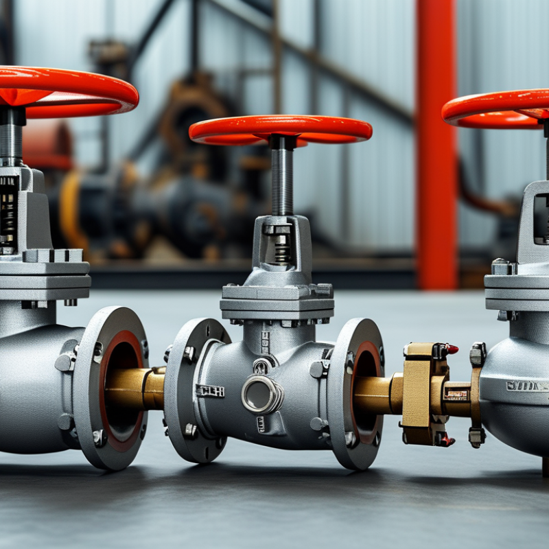
Different valve designs suit different duties. Ball valves usually provide quick isolation, while globe valves offer finer throttling. Butterfly valves can handle large pipelines with less weight. Check valves work differently because they respond to flow direction rather than a direct control signal. Selection depends on pressure, temperature, fluid properties, leakage requirements, and maintenance access.
A correct installation still needs verification. Technicians inspect connections, actuator travel, instrument signals, and emergency shutdown functions. Manufacturer instructions and recognized engineering standards should guide each decision. A valve that looks suitable may perform poorly under vibration or abrasive service. That assumption can fail.
Good valves control also depends on routine testing. Operators should watch for unusual noise, slow movement, unstable readings, and visible leakage. No system is perfect. Even a well-designed loop may need recalibration after months of service. Understanding how each component behaves makes troubleshooting more accurate and improves long-term reliability.
Definition and Purpose of Valve Control
Valve control is the method of regulating fluid movement inside a process system. It adjusts flow, pressure, temperature, or liquid level through a controlled change in valve position. A controller compares the measured condition with the target value. It then sends a signal to an actuator, which opens or closes the valve.
The purpose is practical: keep production stable, protect equipment, and reduce wasted energy. A temperature sensor may detect overheating in a heat exchanger. The controller then restricts steam flow by moving the valve toward a safer position. Small movements matter. Poor sizing can create noise, vibration, or unstable flow. In my experience, operators often blame the actuator first. The real problem is frequently an incorrect control range or a blocked sensor.
Industry data shows why this work deserves careful attention. The International Energy Agency reported in Energy Technology Perspectives 2023 that industry consumes about 37% of global final energy. The U.S. Department of Energy’s Industrial Decarbonization Roadmap also identifies process efficiency as a major emissions-reduction opportunity. Valve control cannot solve every efficiency problem, but it can prevent unnecessary pumping, heating, and throttling losses. A 2021 technical assessment under IEC 60534 principles recommends evaluating valve characteristics, pressure drop, and controllability together. That approach is sound, though field conditions can still expose gaps in the original design. Regular calibration, trend monitoring, and physical inspection remain essential. Fancy control logic cannot repair a leaking valve.
| Control Dimension | Definition or Function | How It Works | Typical Data or Range | Primary Purpose |
|---|---|---|---|---|
| Valve Control | The regulation of fluid or gas flow by changing a valve’s opening position. | A controller compares the desired process condition with the measured condition and adjusts the valve accordingly. | Valve position: 0% to 100% open | Maintain stable flow, pressure, temperature, or liquid level. |
| Manual Control | A valve is operated directly by a handwheel, lever, or gear mechanism. | An operator observes the process and changes the valve position manually. | Operator-adjusted position; no automatic feedback required | Simple isolation, startup, maintenance, and low-frequency adjustments. |
| On-Off Control | A valve has two principal states: fully open or fully closed. | An electrical, pneumatic, or hydraulic actuator moves the valve between its end positions in response to a command. | Typical command states: 0% or 100% | Start or stop flow and provide process isolation. |
| Modulating Control | A valve can move to intermediate positions to regulate flow continuously. | The actuator receives a variable control signal and positions the valve to match the required process output. | Common command signals: 4–20 mA or 0–10 V | Precise control of flow, pressure, temperature, or level. |
| Control Valve | A powered valve designed to regulate process conditions automatically. | A controller sends a signal to an actuator, which changes the valve opening and therefore the flow resistance. | Position feedback commonly expressed as 0–100% | Automatic process control and improved operating consistency. |
| Actuator | The mechanism that converts a control signal into mechanical valve movement. | It uses pneumatic pressure, electrical energy, or hydraulic power to rotate or move the valve stem. | Common types: pneumatic, electric, and hydraulic | Provide the force and movement needed to operate the valve. |
| Pneumatic Actuator | An actuator powered by compressed air. | Air pressure acts on a diaphragm or piston to move the valve; springs may provide fail-safe movement. | Typical instrument-air pressure: approximately 3–8 bar | Fast response and reliable operation in many industrial environments. |
| Electric Actuator | An actuator powered by an electric motor or electric drive mechanism. | The motor converts electrical energy into rotary or linear motion to position the valve. | Control input may be discrete or analog, such as 4–20 mA | Accurate positioning where compressed air is unavailable or unnecessary. |
| Controller | A device or software function that determines the required valve position. | It calculates the difference between the setpoint and the measured process variable, then issues an output signal. | Common control method: PID control | Reduce process error and maintain the desired operating condition. |
| Setpoint | The desired target value for a controlled process variable. | The controller continuously compares the setpoint with the actual measurement. | Examples: 6 bar pressure, 80°C temperature, or 50% tank level | Define the required operating condition. |
| Process Variable | The actual measured value of the process condition being controlled. | A sensor or transmitter measures the variable and sends its value to the controller. | Flow, pressure, temperature, level, or composition | Provide real-time information for automatic correction. |
| Feedback Signal | A signal indicating the actual valve position or process condition. | The controller uses feedback to verify the response and correct deviations. | Typical analog range: 4–20 mA | Improve accuracy, monitoring, and fault detection. |
| Flow Coefficient | A capacity rating that describes how much fluid can pass through a valve at a defined pressure drop. | A higher coefficient generally indicates greater flow capacity under comparable conditions. | Common engineering terms: Cv or Kv | Support valve sizing and capacity comparison. |
| Pressure Drop | The difference in pressure between the valve inlet and outlet. | The valve creates resistance to flow, and the resulting pressure difference influences the flow rate. | Measured in bar, kPa, or psi | Determine operating performance and energy loss. |
| Fail-Safe Action | The predefined valve position or response used when control power or signal is lost. | Spring-return or other protective mechanisms move the valve to a selected safe state. | Fail-open, fail-closed, or fail-in-place | Protect people, equipment, and the process during abnormal conditions. |
| Response Time | The time required for a valve to move from one position to another after receiving a command. | It depends on actuator size, supply pressure, valve design, load, and control settings. | Specified in seconds for a defined travel or rotation | Evaluate control speed and process stability. |
| Common Applications | Industrial and building systems that require controlled movement of liquids or gases. | Valve control is applied to water, steam, air, fuel, chemicals, and other process media. | Water treatment, HVAC, power generation, manufacturing, and process plants | Automate flow management, improve efficiency, and support safe operation. |
Related Posts
-
Understanding the Role of Guide Valves in Modern Hydraulic Systems
-
How to Choose the Right Guide Valves for Your Project?
-
How to Choose the Right Guide Valves for Your System?
-
Top 10 Guide Valves for Optimal Performance and Efficiency?
-
How to Choose the Best Forged Steel Valves for Your Needs?
-
How to Choose the Right Valve Steel for Your Industrial Applications
